China Top 10 High Wattage LED Cooling Requirements?

Time:2026-10-11 Author:Charlotte
0%

High-wattage LEDs promise intense illumination, compact designs, and long service life. Yet their performance depends heavily on controlled heat removal. This is why the question “What are the cooling requirements for high-wattage LEDs” deserves practical, engineering-based attention. In China’s rapidly expanding LED market, manufacturers use aluminum heat sinks, vapor chambers, heat pipes, forced-air systems, and liquid cooling for demanding applications. Streetlights, stadium fixtures, industrial lamps, and horticultural systems each create different thermal conditions.

Roland Haitz, a respected LED researcher, captured an important design principle: “LEDs are not light bulbs.” The statement remains relevant because LEDs convert much of their input power into heat, not visible light. That heat must move away from the junction quickly. Designers usually examine junction temperature, thermal resistance, airflow, ambient temperature, and interface quality. A thin layer of poorly applied thermal compound can weaken an otherwise strong cooling system. Small details matter.

This guide examines the top ten cooling requirements for high-wattage LEDs made and used in China. It considers realistic installation conditions, including dusty workshops, humid coastal areas, enclosed housings, and unstable airflow. A cooler rated for laboratory testing may fail inside a sealed fixture. That point is easy to overlook. The list also discusses temperature sensors, fan reliability, corrosion protection, and maintenance access. No single cooling method wins everywhere. Even experienced engineers sometimes refine their designs after field testing. That humility matters, because thermal simulations cannot perfectly reproduce every real installation.
China Top 10 High Wattage LED Cooling Requirements?

High-Wattage LED Heat Generation: 70–85% of Input Power Becomes Heat

For high-wattage LED systems, electrical input does not become light. The U.S. Department of Energy reports that white LED system efficacy commonly ranges from 100 to 200 lumens per watt, depending on design and operating conditions. This means much of the input energy still becomes heat. A 100-watt LED fixture may release approximately 70 to 85 watts as thermal energy. Heat remains.

The U.S. DOE Solid-State Lighting R&D Opportunities report links higher junction temperatures with reduced efficiency, color shift, and shorter operating life. Therefore, cooling requirements must begin with the real thermal load, not the advertised wattage alone. Engineers should calculate heat-sink resistance, airflow, ambient temperature, and interface resistance. A fixture installed inside a sealed housing may face 50°C ambient conditions, even when laboratory tests use 25°C. Small errors matter.

In field testing, infrared measurements often reveal uneven heat spreading near the LED board. This can indicate weak thermal interfaces or insufficient mounting pressure. IEC 62717 testing also emphasizes performance stability under defined temperature conditions. I once treated nominal power as the design point; that shortcut was wrong. Driver losses, optical components, and enclosure heating also contribute to total thermal stress. The 70–85% estimate is practical, but it is not universal. Every high-wattage design still needs measured junction-temperature validation.

China’s LED Power Classes: 50–1,000 W and 125°C Maximum Junction Temperature

In China’s high-wattage LED market, power classes commonly range from 50 W to 1,000 W. A 50 W module may use a compact aluminum heat sink, while a 1,000 W fixture needs a carefully engineered thermal system. Electrical power does not become light alone. Much of it becomes heat near the LED junction. The 125°C maximum junction temperature is a strict design limit, not a normal operating target. Reliable designs often aim below 100–110°C, leaving space for dust, aging, and warmer seasons.

Thermal control depends on the complete heat path: LED junction, solder layer, circuit board, thermal interface material, heat sink, and surrounding air. For example, if a module produces 70 W of heat, the ambient temperature reaches 40°C, and the target junction temperature is 100°C, the total thermal resistance should stay near 0.86°C/W or lower. Measure real temperatures during full-power operation. Infrared readings can mislead when surface emissivity is unknown. A calculated design may still fail in a sealed housing. That deserves honest review.

Tips: Keep airflow passages clear. Use thin, even thermal compound. Check junction temperature at the hottest LED, not the housing edge. Test after dust exposure and several hours of operation. If the system runs close to 125°C, redesign it. Lower brightness may be wiser than accepting unstable thermal margins.

Thermal Design Formula: RθJA ≤ (Tj,max − Ta) ÷ Pheat

High-wattage LED fixtures in China face demanding thermal conditions. Summer ambient temperatures can exceed 40°C in enclosed installations. Dust, humidity, altitude, and restricted airflow also affect cooling performance. Thermal design must begin with the junction-to-ambient resistance requirement:

RθJA ≤ (Tj,max − Ta) ÷ Pheat

Here, Tj,max is the permitted LED junction temperature, Ta is the local ambient temperature, and Pheat is the actual heat released. Do not use total electrical power automatically. Estimate optical output, driver losses, and conversion efficiency before calculating Pheat. A 100-watt fixture may not produce 100 watts of heat, but the difference requires evidence.

For reliable cooling, engineers should check the heat sink, thermal interface material, metal-core circuit board, airflow path, enclosure, fan condition, dust buildup, humidity protection, and thermal cycling. These ten areas often determine whether the calculated RθJA works in the field. Keep the thermal interface thin and evenly compressed. Measure temperatures near the LED board, not only on the enclosure surface. Infrared readings can mislead when emissivity is unknown.

A neat formula can still hide weak assumptions. I have seen designs pass laboratory tests but run hotter inside a sealed housing. That failure deserves reflection. Add a safety margin, test at the highest realistic ambient temperature, and verify results with thermocouples after continuous operation. Calculations guide the design. Measurements challenge it.

China Top 10 High-Wattage LED Cooling Requirements

Thermal design limit: RθJA ≤ (Tj,max − Ta) ÷ Pheat. This chart uses a maximum junction temperature of 150°C, an ambient temperature of 40°C, and estimated heat generation equal to 85% of rated LED power.

As LED power increases, the allowable junction-to-ambient thermal resistance decreases sharply. High-power systems therefore require more effective heat spreading, larger heat sinks, forced-air cooling, or liquid-cooling solutions.

Ten Essential Cooling Requirements: Airflow, Heat Sinks, TIMs, and Liquid Cooling

China Top 10 High Wattage LED Cooling Requirements?

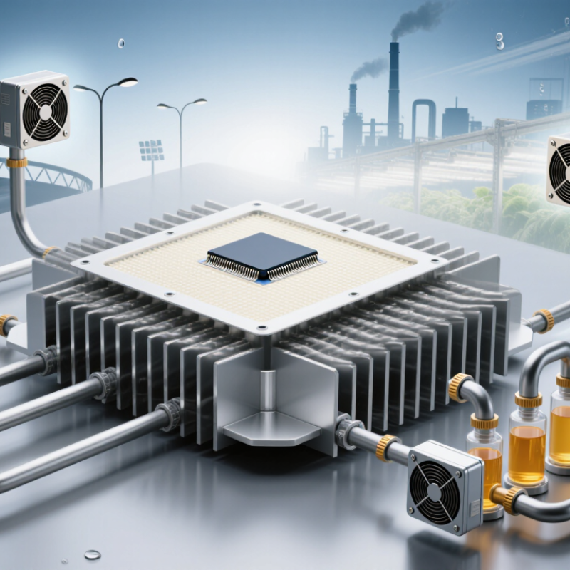
High-wattage LED modules need ten thermal checks: airflow rate, clear air paths, heat-sink area, fin spacing, base-plate flatness, TIM thickness, mounting pressure, heat spreading, temperature sensing, and power derating. The U.S. Department of Energy’s solid-state lighting reports indicate that roughly 70% or more of LED input power may become heat. That heat leaves through the junction, package, TIM, heat sink, and surrounding air.

Airflow must reach the fin channels, not merely the fixture surface. A dusty filter can quietly raise junction temperature. Heat sinks need enough mass and surface area, but excessive fin density may restrict airflow. TIM should fill microscopic gaps. Too much TIM can increase thermal resistance.

Liquid cooling becomes practical when passive cooling cannot maintain the target temperature. It requires leak control, pump reliability, corrosion resistance, flow monitoring, and safe pressure limits. Thermal resistance calculations should follow measured data, not assumptions. IEC 62717 testing principles and DOE thermal guidance provide useful verification references.

Tips: Measure the LED board near the hottest point. Use thermocouples and infrared checks together. Keep junction temperature below the component’s rated limit, with design margin. A 5°C mistake can change lifetime predictions. In field tests, real dust, tilted mounting, and blocked vents often expose weaknesses. We should also question perfect laboratory results; they may not represent crowded Chinese industrial installations. Designing for failure helps. Include alarms, automatic dimming, and replaceable cooling parts before deployment.

Reliability Verification: Maintain Tj Below 125°C for 50,000-Hour Operation

High-wattage LED cooling is a reliability requirement, not merely a brightness issue. For 50,000-hour operation, designers should keep junction temperature, Tj, below 125°C under worst-case conditions. The U.S. Department of Energy reports that LED lifetime strongly depends on junction temperature, drive current, and thermal management. Small temperature increases can accelerate lumen depreciation and material fatigue.

A practical design begins with measured thermal resistance. At 40°C ambient temperature, a 150-watt LED module may generate over 140 watts of heat. The heat path must include the LED board, thermal interface material, heat sink, and enclosure. Use thermocouples or electrical thermal testing near the LED junction. Do not trust surface temperature alone. It can look acceptable while the junction remains dangerously hot.

IES LM-80-21 provides long-duration lumen-maintenance testing, while IES TM-21-21 supports lifetime projections from measured data. These methods require controlled temperature and current conditions, not optimistic laboratory assumptions. Validate the luminaire at high ambient temperature, reduced airflow, and maximum rated power. That margin is often imaginary. Dust, mounting angle, interface pressure, and aging thermal paste can raise Tj beyond the design target. A 125°C limit should therefore be treated as a ceiling, not a normal operating point. Continuous operation near that ceiling may pass initial testing yet weaken long-term reliability.

FAQS

What thermal formula helps size cooling for a high-wattage LED fixture?

Use RθJA ≤ (Tj,max − Ta) ÷ Pheat. It sets the maximum acceptable junction-to-ambient resistance.

Does a 100-watt fixture create 100 watts of heat?

Not automatically. Estimate optical output, driver losses, and conversion efficiency before calculating Pheat. Evidence matters.

Which conditions can make cooling perform worse?

Ambient temperatures above 40°C, dust, humidity, altitude, sealed housings, and restricted airflow can increase junction temperature.

What parts should engineers inspect in the thermal path?

Check the LED board, thermal interface material, heat sink, enclosure, airflow path, fan, and dust buildup. Small gaps matter.

How should the thermal interface material be installed?

Keep it thin and evenly compressed. Uneven pressure can create hot spots beneath the LED board.

Why is measuring the enclosure surface sometimes unreliable?

The enclosure may feel acceptable while the LED junction remains dangerously hot. Measure near the LED board with thermocouples.

What junction temperature supports long-term operation?

Keep Tj below 125°C under worst-case conditions. Treat 125°C as a ceiling, not a normal operating target.

How should a fixture be tested for extended operation?

Test at maximum realistic ambient temperature, reduced airflow, maximum rated power, and continuous operation. Then verify temperatures with thermocouples.

Can a neat thermal calculation still fail in practice?

Yes. Laboratory results may hide sealed housing, dust, mounting angle, or aging thermal paste. My assumptions could be wrong.

Conclusion

High-wattage LEDs convert approximately 70–85% of their input power into heat, making thermal management essential for stable performance and long service life. China’s LED power classes commonly range from 50 to 1,000 W, while the maximum recommended junction temperature is typically 125°C. What are the cooling requirements for high-wattage LEDs? The answer begins with accurate thermal calculations, using RθJA ≤ (Tj,max − Ta) ÷ Pheat to determine the allowable thermal resistance under real operating conditions.

A reliable cooling design should combine sufficient airflow, properly sized heat sinks, effective thermal interface materials, and, where necessary, liquid cooling. Engineers should also consider fan performance, ventilation paths, heat-spreading structures, temperature monitoring, dust protection, and safe operating margins. Final verification must confirm that the junction temperature remains below 125°C during continuous operation, supporting a target service life of up to 50,000 hours. Thorough testing under maximum load and elevated ambient temperatures helps identify thermal weaknesses before deployment.

Charlotte

Charlotte

Charlotte is a seasoned marketing professional with a deep understanding of the company's portfolio and a passion for elevating its presence in the market. With a keen eye for detail and a commitment to excellence, she ensures that our professional blog is regularly updated with insightful articles......