A dark, incomplete, or flickering digit can make a simple circuit feel surprisingly difficult. This guide explains How to troubleshoot a 7 segment LED display error through practical, measurable checks. It focuses on common failures, including incorrect pin connections, damaged segments, weak power supplies, faulty resistors, and decoder timing problems.
Electronics educator Ben Eater offers a useful troubleshooting principle: “Measure the signal at each stage.” That advice fits seven-segment displays perfectly. Check the supply voltage first, then inspect the common-anode or common-cathode connection. A multimeter can reveal whether each segment receives the expected voltage. A current-limiting resistor should also be present and correctly rated. Never trust a wiring diagram without comparing it against the actual display pinout.
Experience matters here. I have seen a display blamed for an error caused by one reversed connector. A loose jumper can imitate a failed LED. Software may also send the wrong binary code, creating a convincing hardware fault. That assumption can be wrong.
Look closely at the display under steady light. Does only one segment stay dark? Does every segment glow faintly? Does the fault appear after several minutes? These details narrow the cause quickly. The guide will connect visible symptoms with reliable tests, while acknowledging an uncomfortable truth: some failures need replacement, not repair. Clear measurements, careful documentation, and patience provide the safest path toward an accurate diagnosis.
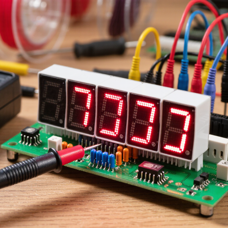
Before testing, identify the display type. A common-cathode unit connects shared pins to ground, while a common-anode unit connects shared pins to positive voltage. A wiring diagram helps, but do not trust it blindly. Check the pinout with a multimeter and a current-limiting resistor. Count the digits and locate the decimal-point pins. I once assumed a four-digit module matched an older layout. It did not, and several segments stayed dark.
Define the error clearly. Is the display blank, dim, flickering, or showing incorrect characters? A blank display may indicate reversed polarity, missing power, or a disabled control line. One dark segment can suggest a damaged LED, loose connection, or incorrect segment mapping. If every character looks wrong, the display type or software logic may be mismatched. Measure voltage at the module pins, then test each segment separately. Record the readings. My first diagnosis was sometimes too quick, especially when intermittent wiring looked like a failed display.
Tips: Use a resistor during direct segment tests. Mark each pin on paper. Compare the observed pattern with the expected character table. Check brightness across all digits. If symptoms change when wires move, inspect the connection before replacing components. Leave room for doubt; a partially working display can hide two separate faults.
2026 How to Troubleshoot a 7 Segment LED Display Error?
Check Power Supply, Wiring, Polarity, and Connector Condition
A dark or partly lit 7 segment LED display often has a simple electrical cause. Begin with the power supply. Safety matters. Switch off power before touching exposed terminals. Then measure the supply voltage with a reliable multimeter. Compare the reading with the display’s rated voltage and controller specification. A low reading may indicate an overloaded adapter, loose terminal, or damaged cable. Check voltage again while the display is operating, because some faults appear only under load.
Inspect every wire against the wiring diagram. Look for reversed segment lines, broken insulation, and terminals inserted into the wrong positions. Confirm whether the display uses common anode or common cathode polarity. Reversed polarity can leave all segments dark or create unusual patterns. Check current-limiting resistors as well. Missing or incorrect resistance can damage segments and produce uneven brightness. Do not trust wire color alone.
Examine the connector closely. Bent pins, dust, moisture, and light oxidation can interrupt individual segments. Gently reseat the connector after power is removed, then test continuity from the controller to each display pin. I once blamed the display, but a loose crimp caused the fault. That mistake still influences my checks. Use the schematic, measured values, and visible evidence together. Avoid replacing parts before confirming the failure point. Sometimes my first assumption is wrong. That is useful feedback.
When a 7-segment LED display shows missing bars, begin with a visual inspection. Look for cracked solder joints, bent leads, or darkened segments. I usually photograph the wiring before removing anything. It prevents a surprisingly common repair mistake.
Power the circuit down before checking resistance or continuity. Use diode-test mode with a current-limited meter. Touch the probes across each segment and record the forward-voltage reading. A healthy segment may glow faintly. Reverse the probes if nothing appears, because the display may use a common anode or common cathode. Test the common pin separately. An open common pin can make every segment appear defective. I once replaced a display when the real fault was one loose connector.
If the segments test correctly, inspect the driver path. Check each series resistor for the correct value and signs of heat damage. Measure transistor control pins while the circuit operates, but avoid shorting adjacent pins. A driver output stuck high or low can hold one segment continuously on. For integrated drivers, compare supply voltage, ground continuity, and logic signals with the circuit diagram. An oscilloscope helps reveal missing pulses, though a multimeter can still identify steady faults. My early checks were too fast; I now test one segment at a time and label every wire. This takes longer, but it reduces false conclusions.
A blank or confusing 7 segment display often begins with control signals. I check the circuit with a multimeter before replacing parts. Confirm the common pin type, then verify whether the controller uses active-high or active-low logic. One reversed assumption can create a completely dark display. It happened during a recent prototype test.
Use an oscilloscope to inspect segment and digit-enable lines. The waveform should switch cleanly, without irregular pauses or unexpected voltage levels. For multiplexed displays, check the refresh rate and duty cycle. Flicker may indicate slow scanning or incorrect timer settings. Measure each current-limiting resistor directly on the board. A damaged resistor can produce one dim segment, while an absent resistor may overload the LED.
Firmware settings deserve equal attention. Confirm the segment bit order, decimal-point mapping, output mode, and logic polarity. A display showing “E” instead of “8” may have a wiring or lookup-table error. Check the microcontroller’s pin configuration after every reset. I once blamed a loose connector, but the real fault was an input pin left floating. That mistake was avoidable. Record measured voltages, resistor values, and firmware changes during testing. Clear notes make repeated faults easier to verify and help another technician reproduce the diagnosis.
2026 How to Troubleshoot a 7 Segment LED Display Error?
Replace Faulty Parts and Verify Stable Display Operation
A dark segment does not always mean a failed display. Inspect the supply voltage, ground path, connector pins, and current-limiting resistors first. Measure voltage directly across the module while it operates. A stable reading matters more than a quick bench test. If one segment remains dim, compare its forward voltage with a working segment. Unequal readings can indicate a damaged LED junction or driver output. Replace the faulty display, resistor, transistor, or driver only after confirming the defective part. Otherwise, the new component may fail again.
Keep wiring short and secure. Check for cracked solder joints around the common pins. Thermal stress can create intermittent faults that appear only after several minutes. The U.S. Department of Energy’s Solid-State Lighting R&D Opportunities report states that temperature and drive current strongly influence LED lifetime. This principle applies to seven-segment modules, even when their package is small. Uptime Institute’s 2024 Annual Outage Analysis reported that 54% of respondents experienced a recent outage costing more than $100,000. That figure reinforces the value of stable power verification, even in compact control panels. Test the repaired display for at least 30 minutes. Cycle every numeral, inspect brightness uniformity, and record supply voltage at startup and under load. I sometimes overlook connector movement during testing. That mistake is avoidable. Secure the assembly, repeat the test, and confirm the display remains steady.
Check the supply voltage, ground path, connector, and common pin type. Confirm whether the circuit uses active-high or active-low logic. One reversed assumption can darken every segment.
Use an oscilloscope on the segment and digit-enable lines. Clean waveforms should switch without long pauses or unexpected voltage levels. Irregular signals suggest wiring, timing, or controller problems.
Inspect the refresh rate and duty cycle. Slow scanning or incorrect timer settings can create visible flicker. Check the timing values.
Measure its current-limiting resistor directly on the circuit board. Compare its forward voltage with a working segment. A damaged resistor, LED junction, or driver output may be responsible.
Yes. An absent current-limiting resistor may overload the LED segment. Replace parts only after confirming the measured resistance and operating voltage.
Check the wiring, segment bit order, and lookup table. Also verify decimal-point mapping and logic polarity. The visual error may come from firmware, not the display module.
Review the microcontroller pin configuration after every reset. An input pin left floating can produce unpredictable segment behavior. I once blamed a connector instead.
Run the display for at least 30 minutes. Cycle every numeral, inspect brightness uniformity, and measure voltage at startup and under load. Move the connector gently. Intermittent faults sometimes hide there.
How to troubleshoot a 7 segment LED display error begins with identifying the display type, such as common anode or common cathode, and clearly defining the symptom. Determine whether the display is completely blank, showing incomplete numbers, flickering, or presenting incorrect segments. Then inspect the power supply, wiring, polarity, and connectors for loose contacts, damaged cables, unstable voltage, or reversed connections.
Next, test each LED segment and the common pins with suitable equipment, while checking driver components for signs of failure. Inspect current-limiting resistors, control signals, and microcontroller settings to confirm that the correct logic levels and segment patterns are being delivered. If a defective LED, connector, resistor, driver, or control component is found, replace it with a compatible part. Finally, recheck the wiring, operate the display through several numbers and symbols, and monitor it for flickering, overheating, or repeated errors to verify stable and reliable operation.

Zever Light